Describe the Half Wave Rectifier Using a Diode
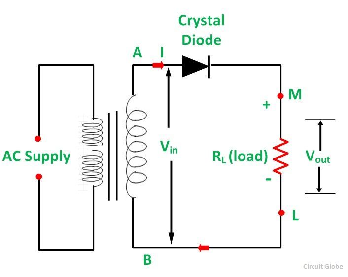
The secondary coil is connected to the diode in series with a resistance RL called the load resistance. Half-wave Rectifier Circuit Schematic Diagram.
What Is Diode What Is Rectification How Can You Use A Diode For Half Wave Rectification Quora
May 5 2020 by admin.
. We briefly go over the steps of creating a useable DC. TI input is sinusoidal waveform with a frequency of 60 Hz. The ac input signal to be rectified is fed to the primary P coil of the transformer.
Assuming an ideal diode sketch V V. This can be done by using the semiconductor PN junction diode. P-n junction diode and the source of ac voltage all connected in series.
Moving from theory to a practical demonstration we show how a half wave rectifier works in real life. Assuming an ideal diode sketch Vị Va and ia for the half-wave rectifier below. The 220V input is a sine wave AC.
The alternating voltage source is connected to the primary coil of a transformer. During the positive half of the input signal suppose P 1 and P 2 are negative and positive respectively. With a neat sketch explain the working of full-wave rectifier.
Half-wave rectifiers are used to convert AC voltage to DC voltage and only require a single diode to construct. Half Wave Rectifier Full Wave Rectifier. The input is sinusoidal waveform with a frequency of 60 Hz.
The flow of current in the load resistance RL is from A to B. Rectification is an application of the pn junction diode. A single phase half wave controlled rectifier is a thryristor based circuit which produces output voltage for positive half of the supply voltage.
In the first phase of current let the current flow in clockwise direction in the circuit. We use only a single diode to construct the half wave rectifier. Half-wave rectifiers transform AC voltage to DC voltage.
This is the reason. Thus converts the AC voltage into DC voltage. The rectifier circuit cosists of resistive load rectifying element ie.
Here we will only talk about the main rectifier circuit. And i Ideal. The half wave rectifier is the simplest form of the rectifier.
The rectifier which converts only one half of ac into dc is called half-wave rectifier. A half wave rectifier is a device that lets only a single half of the alternating current voltage waveform to pass blocking the other half. Also determine and sketch V.
The half wave rectifier is made up of an AC source transformer step-down diode and resistor load. Basic AC-DC Converter Using Four Diodes. Three-phase half-wave rectifier a Describe the waveform of the rectifier output voltage with respect to the waveform of the source voltage waveform and explain describe the diode conduction sequence to assist your answer.
Describe a half-wave rectifier using a diode. The structure of this half-wave rectifier circuit is very simple. The main application of tangency diode is in rectification circuits.
However the phase relationship between the initiation of load current and supply voltage can be controlled by changing firing angle. Half wave rectifiers make use of the diode as it allows only a single way flow of the current. Half-wave rectifiers produce far more ripple than full-wave rectifiers and much more filtering is needed to eliminate harmonics of the AC frequency from the output.
Explain the rectifying action of a diode. The diode allows the current to flow only in one direction. Rectifiers yield a unidirectional but pulsating direct current.
During the negative half cycle the diode is reverse biased and it is equivalent to an open circuit hence the current through the load resistance is zero. Half-wave rectification requires a single diode in a single-phase supply or three in a three-phase supply. These circuits are wont to describe the conversion of ac signals to dc in power supplies.
B Explain the relationship between the RMS value of the load voltage and the RMS value of the ac voltage. So to understand the underlying theory behind a half wave rectifier you need to understand the pn junction and the characteristics of the pn junction diode. 6 rows Diode as a Rectifier.
The circuit diagram of a half wave rectifier using a junctiondiode is as shown in fig. It is called phase controlled half wave rectifier. The diode acts as infinite resistance and there is no current in the circuitSo the the open points experience current only.
In Half Wave Rectifier when the AC supply is applied at the input a positive half cycle appears across the load whereas the negative half cycle is suppressed. The main application of. This would mean that S 1 and S 2 are positive and negative respectively.
As the spaces between each half-wave developed by each diode is now being filled in by the other diode the average DC output voltage across the load resistor is now double that of the single half-wave rectifier circuit and is about 0637V max of the peak voltage assuming no losses. A half wave rectifier is defined as a type of rectifier that only allows one half-cycle of an AC voltage waveform to pass blocking the other half-cycle. Full wave Rectifier and Half wave Rectifier.
A halfwave rectifier is defined as a type of rectifier that allows only one-half cycle of an AC voltage waveform to pass while blocking the other half cycle. And ig for the half-wave rectifier below. This problem has been solved.
521 Describe the function of semiconductor diode 522 Communicate about the function of semiconductor diode and capacitor as a rectifier. Explain how zener diode maintains constant voltage across the load. The diode is placed between the transformer and resistor load.
The secondary S coil is connected to the junction diode through a load resistance R L. The input and output voltage waveform may be analytically written as. Half wave rectifier.
A half wave rectifier is a device which makes use of key properties of a pn junction diode. While converting AC to DC voltage only one diode is used to construct. The diode allows the current to flow through it so the open points have a current flowing through it.
The main component is a diode as shown in the schematic diagram below. To ontain the desired dc voltage across the load the ac voltage is applied to rectifier circuit using suitable step-down step-up transformer mostly a step-down one with necessary turns ratio. Thus the diode conducts only for one half cycle and results in half wave rectification.
Half-wave Rectifier Circuit. A halfwave rectifier circuit uses only one diode for the transformation. Therefore the diode D 1 is forward biased and D 2 is reverse biased.
In the next phase the current flows in ant clockwise direction.

Half Wave Rectifier Circuit Diagram Theory Applications

Half Wave Rectifier Circuit Diagram Theory Applications
Working Of Half Wave Rectifier Sale Online 51 Off Tercesa Com
No comments for "Describe the Half Wave Rectifier Using a Diode"
Post a Comment